Arduino Based Digital IC Tester Using MATLAB
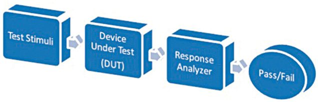
Testing of digital electronic systems generally involves applying a set of test stimuli to inputs of the device-under-test (DUT) and analysing responses of the system using a response analyser. If the DUT generates correct output responses (also called the golden response) for all the input stimuli, the DUT is regarded as fault-free. Those DUTs that fail to meet the golden response are regarded as faulty or defective. Block diagram for testing a device is shown in Fig. 1.
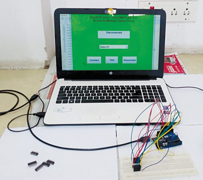
This project describes testing of 74xx series digital ICs using a MATLAB graphical user interface (GUI) drop-down menu based approach. MATLAB acts as the test stimuli generator to the IC, which is the DUT. The GUI initiates communication with the Arduino and provides a user-friendly and interactive approach to conduct the test. The MATLAB source program (ic_tester.m) acts as the response analyser and displays test results on the front panel of the GUI.
Circuit and working
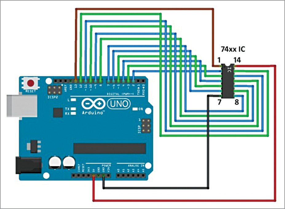
Circuit diagram of the Arduino-based digital IC tester is shown in Fig. 4.
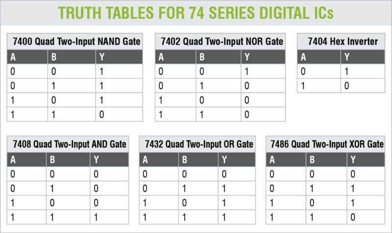
As mentioned earlier, MATLAB is used to apply stimuli to the DUT (74xx series digital ICs) and also record the response of the DUT to stimuli. It then compares the response of the DUT with the correct/golden response to test whether the device is faulty or not. For a digital IC, the correct response is given in the form of a truth table. Acting as a response analyser, the MATLAB verifies each and every possible outcome according to the truth table of a particular IC.
74xx series ICs that can be tested by this project are 7400, 7402, 7404, 7408, 7432 and 7486. Truth tables for these ICs are shown on the next page.
Software
1. Arduino IDE 1.6.5 is used to program the Arduino. The GUI application program has been developed in the R2014a version of MATLAB. The procedure to install the ‘Legacy MATLAB and Simulink Support for Arduino Package’ is described in ‘Controlling a Robotic Car Through MATLAB GUI’ DIY article.
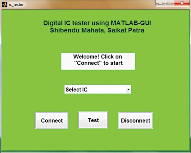
2. After correctly setting up the path for the package, open source code files (ic_tester.m) of this project. Keep both the source code files in the same folder. Edit COM port (in the line a=arduino (‘COM19’)) with the port number in your PC where the Arduino Uno board has been installed. Run the file and click ‘Connect’ button to establish connection between MATLAB and Arduino Uno board. After successful communication is established, select proper IC from the drop-down menu and click ‘Test’ button in the GUI to test the IC.
Download Source Code
Happy Learning
Source: Electronics For You
Dear Mr. Dhiraj Krishnani, can you post a tutorial ON "Automated Toll Tax System" in VHDL.
ReplyDeleteI need full details ( material used , process and etc.) , I decided to work as my BE. mini project, so plz contact to me about this project.
ReplyDelete